Electronics bench & ESP32
USB logic analyzers for ESP32: decode I2C, SPI and UART
Choose Saleae Logic 8 or Logic Pro 8 by bus speed, channel count and USB connection, then capture I2C, SPI and UART traffic with the right decoder settings.
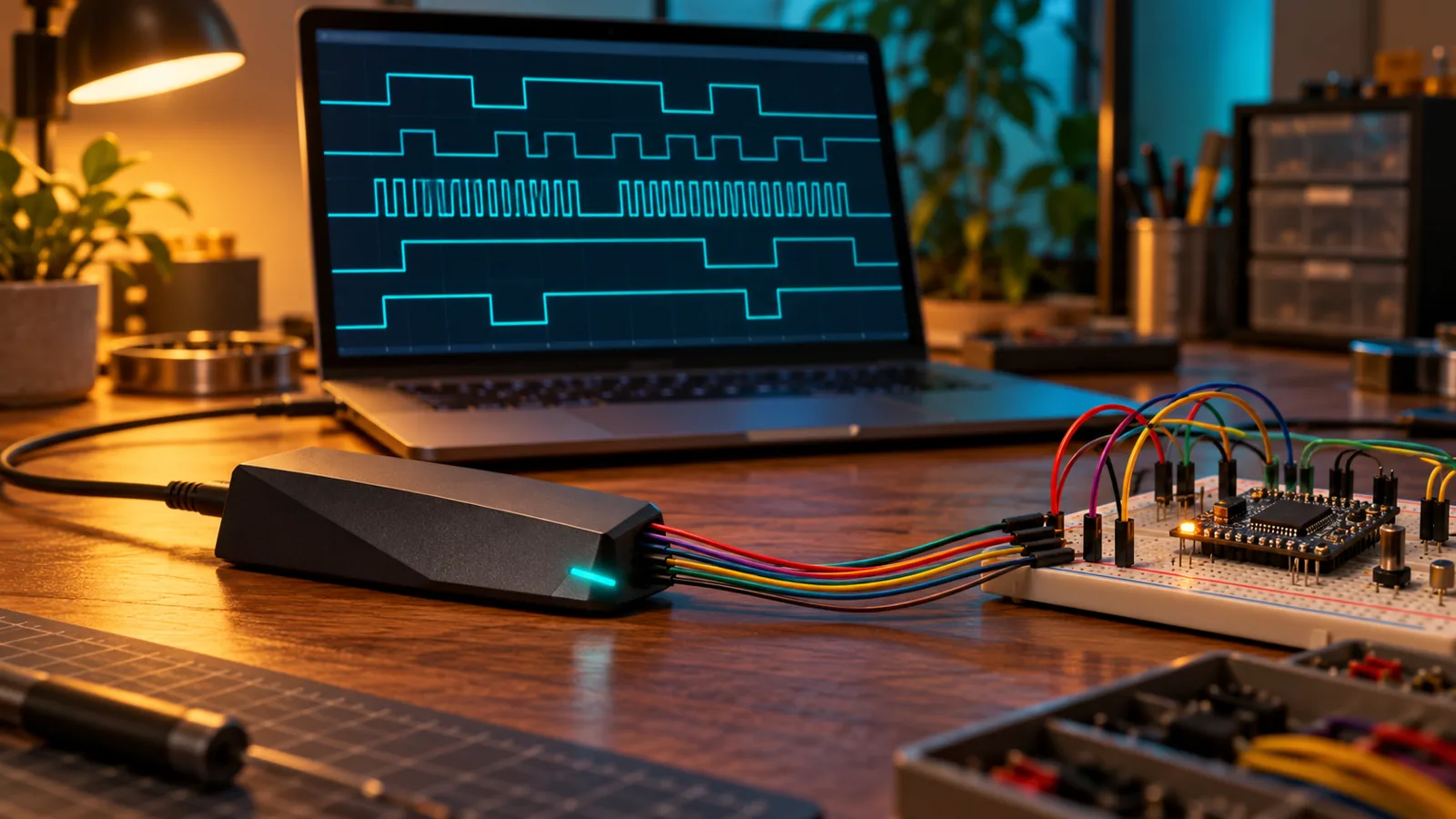
OUR PICKS / YOUR SETUP
Find your fit.
Choose Saleae Logic 8 for I2C and UART sensor projects, or Logic Pro 8 for faster SPI and selectable thresholds. Both have eight inputs and use Logic 2; Pro needs USB 3 for its maximum rates.
- Inputs8 per analyzer
- DecodeI2C · SPI · UART
- SoftwareLogic 2
We earn a commission if you buy through our links — it doesn’t change our picks. How we make money → As an Amazon Associate I earn from qualifying purchases.
YOUR NEXT PROJECT / THE GEAR
Parts list
- Saleae Logic 8 (red)Check price on Amazon
Capture I2C and UART on eight inputs with the Logic 2 decoder workflow.
- Saleae Logic Pro 8Check price on Amazon
Choose higher digital rates and selectable thresholds for a broader debugging bench.
Your ESP32 is asking the sensor a question. Is the sensor answering? A USB logic analyzer lets you read that conversation instead of guessing from an empty dashboard. Choose Saleae Logic 8 for I2C and UART sensor projects, or Logic Pro 8 for faster SPI and selectable input thresholds.
Sources: research-based picks from Saleae’s datasheets and protocol guides, checked November 1, 2026.
Buy for the bus you want to read
A logic analyzer records digital transitions and decodes them into transactions. It is the next step when the meter and wiring tools on your electronics bench have answered the basic power and continuity questions.
Count the signals first. I2C uses SDA and SCL. A UART direction needs one data input; observing both directions takes another. A typical SPI capture uses clock, MOSI, MISO and chip select. Both picks have eight inputs, leaving room to watch another control line alongside the bus.
| Pick | USB connection | Maker maximum digital rate | Fit |
|---|---|---|---|
| Saleae Logic 8, red | USB 2 High Speed | 100 MS/s with up to 3 channels | I2C and UART sensor debugging |
| Saleae Logic Pro 8, black | USB 3 SuperSpeed for maximum rates | 500 MS/s with up to 4 channels | Faster SPI and selectable thresholds |
The Logic 8 datasheet lists two four-channel harnesses, 16 test clips, a USB cable and carrying case. The Logic Pro 8 datasheet lists the same harness-and-clip count with a USB 3 cable. Both use Logic 2 on Windows, macOS or Linux. Start with those included leads.
Why the channel count changes the answer
The headline rate applies to a limited number of enabled inputs. Logic 8 specifies 50 MS/s with up to six digital channels and gives an eight-channel example at 25 MS/s. Pro 8 gives an eight-channel digital example at 100 MS/s over USB 3. Its USB 2 fallback gives you lower available rates.
Here is the buying difference in a concrete example. Saleae recommends sampling SPI at least four times faster than its clock:
25 MHz SPI clock × 4 samples per clock = 100 MS/s minimumThat is a calculated planning example. Saleae explicitly recommends Pro 8 or Pro 16 over USB 3 for this four-channel, 25 MHz SPI job. For a 100 kHz I2C bus, its recommendation is 1 MS/s or faster. Pick around the actual bus, then check the rate available with your channels enabled.
Make the connections count
Power the board off before attaching clips. Use its documented low-voltage signal pins, connect analyzer ground to the same ground reference as the PC and board, and keep ground clips away from powered rails. The inputs share ground with each other and the PC; follow Saleae’s grounding guidance.
Match the logic voltage too. Both models support ordinary 3.3 V logic; Pro 8’s selectable threshold setting applies to all inputs together. Select for the bus you are observing, rather than assuming each input has its own independent voltage setting.
Your first capture: listen to an I2C sensor
The ESPHome temperature, motion and light build gives you a documented board pinout and an I2C sensor project to investigate. Keep the sensor connected to the controller; the analyzer observes the existing bus.
- Identify SDA, SCL and ground from the board and sensor documentation, then attach the corresponding analyzer leads with power off.
- In Logic 2’s Device Settings, enable the two digital inputs you used. Leave unused inputs and analog recording off for this first capture.
- Choose a sample rate for the configured bus speed. Restore board power and capture while the controller requests a reading.
- Add the I2C analyzer and assign its SDA and SCL inputs to your recorded channels.
- Look for the address, read/write direction, data and ACK/NAK results. The I2C decoder guide explains those fields and the start/stop markers.
You now have a much better question than “why is it broken?” You can ask whether the controller sent a transaction and whether the addressed device acknowledged it. Save that capture before changing wiring or configuration.
SPI and UART: change the decoder, keep the method
For SPI, assign clock, MOSI, MISO and enable/chip select. Match bit order, bits per transfer, clock polarity, clock phase and enable polarity to the peripheral’s documentation. Clock polarity describes the idle clock level; phase selects the sampling edge. The SPI analyzer guide also explains how to set an unused data input to None.
For UART, add Async Serial, select the captured data input and match bit rate, bits per frame, stop bits, parity and inversion to the source. To observe both directions, add a second decoder for the other input. This is a second software analyzer, not another hardware purchase. See the Async Serial settings guide.
When the decode looks wrong
- A flat trace: check the physical pin and the input selected in software, then capture during actual traffic.
- An unexpected I2C address: the decoder displays seven-bit addresses by default. Compare like with like before changing the firmware.
- Broken I2C frames: zoom into SCL edges for narrow glitches; inspect the connection and voltage setting before applying the decoder guide’s glitch-filter advice.
- UART gibberish or shifted SPI bytes: return to the source’s serial settings or the peripheral’s SPI mode and chip-select assignment.
Keep the capture, channel labels and decoder settings together. Choose Logic 8 when sensor buses are the job, and Pro 8 when faster SPI or selectable thresholds earn their place. Then let the pins tell you what happened.
Sources & methodology
Where these facts come from.
- Saleae Logic 8 datasheet: channels, USB and acquisition limits · checked November 1, 2026
- Saleae Logic Pro 8 datasheet: channels, USB and acquisition limits · checked November 1, 2026
- Saleae sample-rate planning for digital protocols · checked November 1, 2026
- Saleae Logic 2 capture settings · checked November 1, 2026
- Saleae supported logic voltages and threshold controls · checked November 1, 2026
- Saleae grounding and input safety · checked November 1, 2026
- Saleae I2C analyzer setup and ACK/NAK decoding · checked November 1, 2026
- Saleae SPI analyzer channel and mode settings · checked November 1, 2026
- Saleae Async Serial analyzer settings · checked November 1, 2026
Source dates are listed above.
As an Amazon Associate I earn from qualifying purchases.
YOUR NEXT PROJECT / THE GEAR
Parts list
- Saleae Logic 8 (red)Check price on Amazon
Capture I2C and UART on eight inputs with the Logic 2 decoder workflow.
- Saleae Logic Pro 8Check price on Amazon
Choose higher digital rates and selectable thresholds for a broader debugging bench.
Prepared by Racks & Watts.