Electronics bench & ESP32
Current-limited DC bench supplies for ESP32 projects
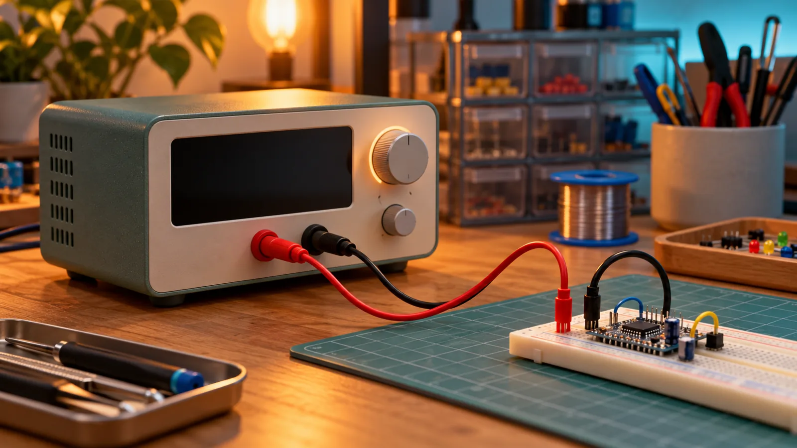
Choose RIGOL DP711, KORAD KA3005P or SIGLENT SPD3303X-E by channels and controls. Learn CV, current limiting, power arithmetic and a careful first connection.
OUR PICKS / YOUR SETUP
Find your fit.
Choose DP711 for one adjustable rail, KA3005P for one rail with USB control, or SPD3303X-E for two adjustable rails plus a selectable output. Set voltage and current from the circuit requirements.
- One railDP711 · KA3005P
- Multiple railsSPD3303X-E
- Know the controlsCV · CC · OCP
We earn a commission if you buy through our links — it doesn’t change our picks. How we make money → As an Amazon Associate I earn from qualifying purchases.
YOUR NEXT PROJECT / THE GEAR
Parts list
- RIGOL DP711Check price on Amazon
Choose one 30 V / 5 A channel with front-panel control and RS232.
- SIGLENT SPD3303X-ECheck price on Amazon
Power separate project rails with two adjustable channels and USB/LAN control.
- KORAD KA3005PCheck price on Amazon
Choose a single 30 V / 5 A programmable channel with USB and RS232.
A board that keeps rebooting deserves a better debugging plan than “try another USB cable.” A bench supply lets you set the voltage, cap the current and watch what the circuit draws. Choose RIGOL DP711 for one adjustable rail, KORAD KA3005P when you want that single-rail job with USB control, or SIGLENT SPD3303X-E when the project needs separate adjustable rails.
Specs and operating guidance from the makers, checked November 1, 2026; this is a research-based guide.
One rail or several?
Start with the circuit, not the biggest wattage figure. An ESP32 board and its sensors may share one suitable input supply. A project with separate logic and peripheral rails benefits from independent channels you can set and switch separately.
| Pick | Output arrangement | Maker-rated adjustable range | Remote interface | Best fit |
|---|---|---|---|---|
| RIGOL DP711 | One adjustable channel | 0–30 V / 0–5 A | RS232 | One rail with a clear front-panel workflow |
| KORAD KA3005P | One adjustable channel | 0–30 V / 0–5 A | USB + RS232 | A single rail with computer control |
| SIGLENT SPD3303X-E | Two adjustable channels + one selectable channel | CH1/CH2 each 0–32 V / 0–3.2 A | USB + LAN | Separate project rails |
The SIGLENT’s third channel selects 2.5, 3.3 or 5 V. Use an adjustable channel when you want to set a particular voltage and current limit for the circuit. The SIGLENT product page lists the channel arrangement; its quick-start manual covers the operating modes and interfaces.
Need the rest of the tools first? Start with the electronics bench guide for the meter, soldering station and breadboard kit.
Voltage is the target; current is the ceiling
For a normal voltage-powered circuit, set its required input voltage and a suitable current limit. In constant-voltage mode (CV), the supply holds that voltage while the circuit draws the current it needs. Setting a higher current limit doesn’t force that current through the board.
When the circuit reaches the limit, constant-current mode (CC) reduces the output voltage to hold the current at the setting. That’s useful information: a board can reset because the supply is limiting current, rather than because its firmware is broken. SIGLENT’s current-compliance explanation describes the transition.
Current limiting and overcurrent protection are different controls. CC regulates the current; OCP can shut the output off when its threshold is crossed. The RIGOL DP700 manual documents voltage/current settings and the separate OVP/OCP controls. Pick the limits from the circuit’s requirements, including startup demand.
DP711: one rail, front and centre
Choose DP711 for a straightforward single-channel bench. Its 30 V / 5 A range gives you room for different low-voltage projects, and its front panel sets voltage, current and protection thresholds. RS232 is the remote-control connection.
The DP700 datasheet makes an important distinction: standard resolution is 10 mV / 10 mA; 1 mV / 1 mA needs the high-resolution option. Choose that option deliberately if finer steps matter to your work. For tiny sleep-current measurements, use a meter suited to that range rather than reading between the supply display’s digits.
KA3005P: a single rail with USB
Choose KA3005P when USB control belongs on your checklist. KORAD’s KA-series model table specifies 0–30 V and 0–5 A for this model, plus USB and RS232 for the programmable P version. Voltage/current adjustment and fast recall keep repeated settings close at hand.
That makes it a useful fit for repeating a power-up routine from a computer while keeping a conventional front panel. Choose the exact KA3005P here; the maker lists other D and upgraded variants separately.
SPD3303X-E: give each rail its own channel
Choose SPD3303X-E when one output is getting crowded. Its two adjustable channels let you power separate parts of a project, with a third selectable-voltage output available. Keep the adjustable channels in independent mode, with series and parallel modes off, for that separate-rail workflow.
USB and LAN suit a bench where you want to save or automate instrument settings. The X-E model’s documented resolution is 10 mV / 10 mA; the similarly named SPD3303X is a different specification. Buy the channel arrangement and interface you need, then follow the exact model’s manual.
A small power example
Assume 5 V, a 0.5 A current limit and a hypothetical load drawing 0.08 A. These are illustration inputs, not ESP32 settings to copy.
| Calculation | Result |
|---|---|
| Output ceiling at the selected voltage: 5 V × 0.5 A | 2.5 W |
| Load power while it draws 0.08 A at 5 V: 5 V × 0.08 A | 0.4 W |
The circuit draws its load current while it stays below the limit. You get a useful readout and a deliberate ceiling, rather than a guess about what the USB source is doing.
Make the first connection
Keep this to low-voltage circuits: match the maker’s input voltage and polarity, disconnect USB and batteries, and make wiring changes with the supply output off.
- Read the board’s power-input instructions. Supply pins, regulator outputs and GPIO are different jobs.
- Set up the instrument. Follow its mains-input instructions; SIGLENT specifically says to unplug the power cord before changing its rear input-voltage selector.
- With the output off, set voltage and current limit. Use the circuit’s documented operating and startup requirements.
- Before attaching the circuit, enable the output and check it with your meter in DC-voltage mode, then switch the output off again. Connect supply positive and negative to the documented input and ground.
- Enable the output and watch CV/CC, voltage and current. If it immediately limits or the board resets, turn the output off and inspect the wiring and expected load before changing the limit.
For the XIAO ESP32C3 used in our first ESPHome sensor build, Seeed’s power-pin guidance requires a diode between an external source and the 5 V pin: anode toward the source, cathode toward the pin. Its 3V3 pin is a regulator output. Follow that board-specific circuit instead of improvising a feed into a spare pin.
Start the sensor build on USB as written, then use the bench supply when you have a power question to answer. The electronics hub has the next projects. A good bench tool earns its space by making the next fault easier to find.
Sources & methodology
Where these facts come from.
- RIGOL DP700 datasheet: DP711 ratings and optional resolution · checked November 1, 2026
- SIGLENT SPD3303X-E channels and controls · checked November 1, 2026
- KORAD KA-series model table and programmable interfaces · checked November 1, 2026
- SIGLENT explanation of constant-current operation · checked November 1, 2026
- RIGOL DP700 manual: voltage/current settings and protection · checked November 1, 2026
- SIGLENT quick start: independent mode, interfaces and mains selector · checked November 1, 2026
- Seeed XIAO ESP32C3 power-pin and diode guidance · checked November 1, 2026
Source dates are listed above.
As an Amazon Associate I earn from qualifying purchases.
YOUR NEXT PROJECT / THE GEAR
Parts list
- RIGOL DP711Check price on Amazon
Choose one 30 V / 5 A channel with front-panel control and RS232.
- SIGLENT SPD3303X-ECheck price on Amazon
Power separate project rails with two adjustable channels and USB/LAN control.
- KORAD KA3005PCheck price on Amazon
Choose a single 30 V / 5 A programmable channel with USB and RS232.
Prepared by Racks & Watts.